Tools required for installation:
- Reciprocal saw (or hand saw)
- Electric Drill Driver
- Tek screws
- Hole saw
NOTE: Turn LOKPOD stack side ways to make it easier to take LOKPODs off one another.
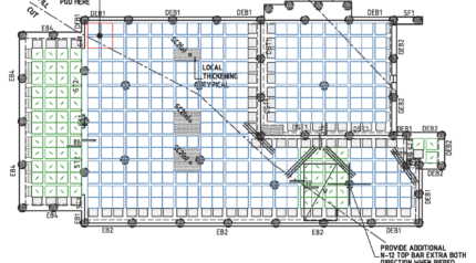
Step 1.
Review engineers drawing to understand site layout and starting point
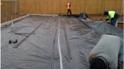
Step 2.
Prepare site, mark out perimeter, plastic film down and formwork installed
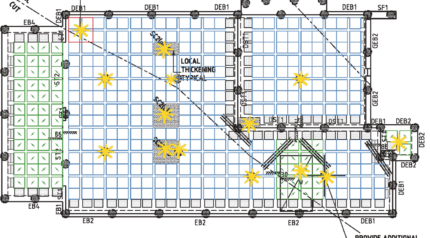
Step 3.
After plastic film is on the ground, spray paint the:
- Starting position
- Pier locations
- Slab thickenings start and finishes
- Beam locations for easy recognition when laying LOKPODs and to ensure complete structural compliance across these sections when pouring concrete
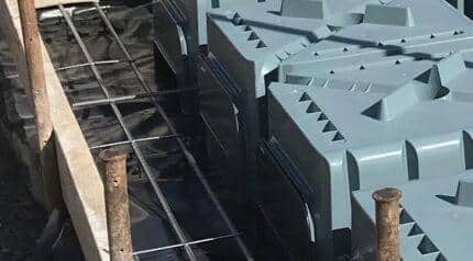
Step 4.
Set perimeter spaces and place reinforcing (trench mesh)
NOTE: If only a ¼ of a LOKPOD needs to be used, use extenders instead of cutting single LOKPOD.
Step 5.
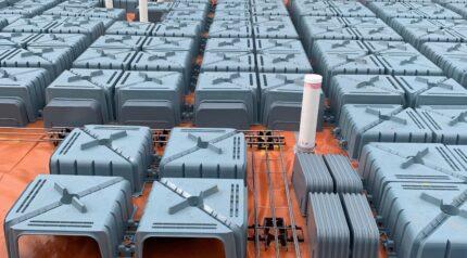
Put down the bulk of the LOKPODs and extenders – skip over any LOKPODs that need to be cut to accommodate for gaps/ pipes and other irregularities
Step 6.
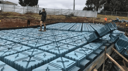
Extenders should be installed under the pod edge to close the opening on the exterior pod sides (teking the extenders
onto the LOKPODs at the correct dimension enhances the installation process)
Step 7.
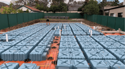
Working your way from the starting position from one side of the slab to the other, LOKPODs will lock and click into one another – ensure the line of LOKPODs is kept straight
Step 8.
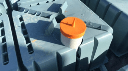
Cut LOKPOD to the required size to accommodate for gaps/pipes and other irregularities (a team member can now start putting down the rebar)
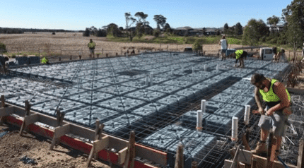
Step 9.
Working your way from the starting position from one side of the slab to the other, LOKPODs will lock and click into one another – ensure the line of LOKPODs is kept straight
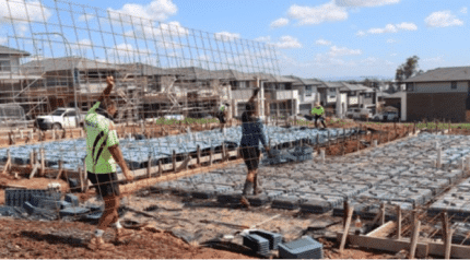
Step 10.
The internal beam bars are laid in the chairing recess - inbuilt between the turrets of the pod. The mesh is then laid on top of the pods – no extra chairs needed. Ensure mesh sits on top of inbuilt chairs and correct cover is retained throughout the slab. Tie in remainder of steel to engineer’s specifications.
Drop edge beams can be formed with extenders and also through incorporation of plastic formboards in a horizontal application and teked on to the uprights, these are consumed in the pour.
